 Kia Forte: Fuel Pump Inspection
Second generation YD (2014-2018) / Kia Forte TD 2014-2018 Service Manual / Engine Control / Fuel System / Fuel Delivery System / Fuel Pump Inspection
[Fuel pump]
| 1. |
Turn ignition switch OFF and disconnect the negative (-)battery
cable.
|
| 2. |
Remove the fuel pump assembly.
|
| 3. |
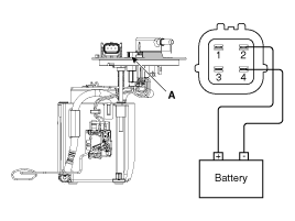
Check motor operation by fuel pump connector (A) connecting power(No.2)
and ground(No.4)
|
[Fuel sender]
| 1. |
Turn ignition switch OFF and disconnect the negative (-)battery
cable.
|
| 2. |
Remove the fuel pump assembly.
|
| 3. |
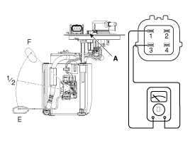
Using an ohmmeter, measure the resistance between terminals 1
and 3 of sender connector (A) at each float level.
|
| 4. |
Also check that the resistance changes smoothly when the float
is moved from "E" to "F".
|
 Fuel Tank Installation
1.
Install in the reverse order of removal.
Fuel tank band installation
nut:
39.2 ~ 54.0 N.m (4.0 ~ 5.5 kgf.m, 28.9 ~ 39.8 lb-ft)
...
 Fuel Pump Removal
[LEV2]
1.
Release the residual pressure in fuel line (Refer to the Fuel
Delivery System - Repair Procedures - "Release Residual Pressure in
Fuel Line ...
See also:
Control Shaft Complete Description
Component location : Control shaft
assembly is mounted on the top of the manual transaxle
Function : Change the gear by shifting
a shift lever. ...
Ignition Coil Removal
1.
Disconnect the battery nagative terminal.
2.
Remove the engine cover.
3.
Disconnect the ignition coil connec ...
Copyright ® www.kifomanual.com 2014-2026


