 Kia Forte: Oil Pump Components
Second generation YD (2014-2018) / Kia Forte TD 2014-2018 Service Manual / Automatic Transaxle System / Hydraulic System / Oil Pump Components

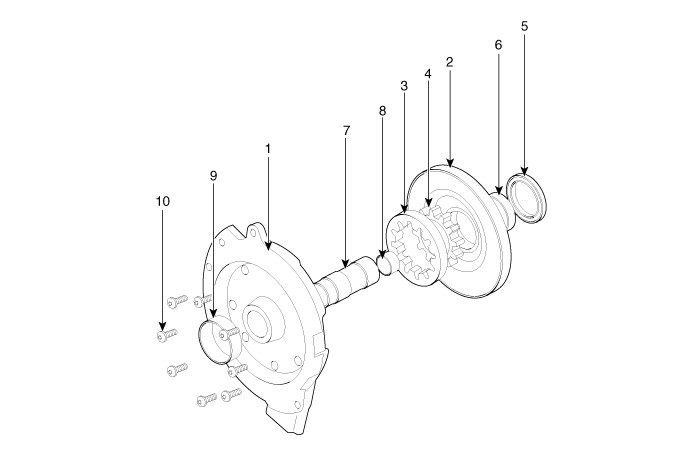
| 1. Oil pump cover 2. Oil pump housing 3. Driven gear 4. Drive gear 5. Oil seal |
6. Bushing-housing 7. Reaction shaft 8. Bushing-reaction shaft 9. Sleeve 10. Bolt |
Oil Pump Operation Flow

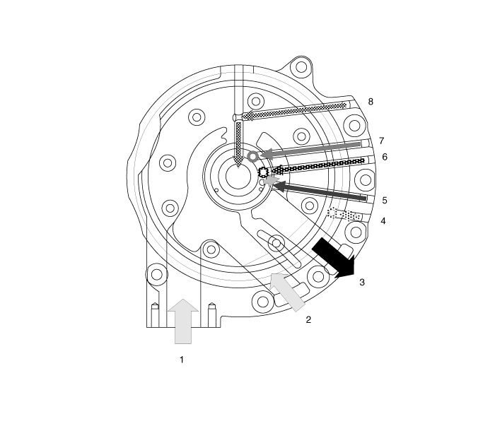
| 1. Inhale(Oil filter) 2. Inhale(Valve body) 3. Outlet 4. 26 Brake (26/B) operation pressure |
5. 35R Clutch (35R/C) operation pressure 6. Lubrication 7. Lock up clutch operation pressure 8. Lock up clutch cancellation |
 Oil Pump Description
The oil pump is built-in as a single unit with the 26 Brake chamber. Rotation
of the pump builds the hydraulic pressure needed for the lubrication of the
various parts of the transaxle and op ...
 Fluid Components Location
1. Injection hole(eyebolt)
2. Oil level plug
3. Oil drain plug
...
See also:
Input Speed Sensor Removal
1.
Disconnect the negative (-) battery cable.
2.
Remove the air cleaner assembly and air duct.
(Refer to Engine Mechanical System - &qu ...
Operation
1.
General Function
A.
Auto-learn takes place only once per Ignition cycle.
B.
On successful compl ...
Sunvisor
Use the sunvisor to shield direct light through the front or side windows.
To use the sunvisor, pull it downward. To use the sunvisor for the side window,
pull it downward, unsnap it from the br ...
Copyright ® www.kifomanual.com 2014-2026
