 Kia Forte: Removal
| 1. |
Turn ignition switch OFF and disconnect the negative (-) battery
cable.
|
| 2. |
Remove the crash pad lower panel.
(Refer to Body - "Crash pad lower panel")
|
| 3. |
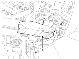
Remove the shower duct (A).
|
| 4. |
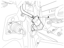
Disconnect the stop lamp switch connector (A).
|
| 5. |
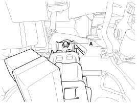
Remove the brake pedal member mounting bolt (A).
|
| 6. |
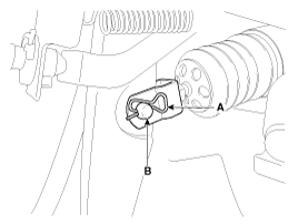
Remove the snap pin (A) and clevis pin (B).
|
| 7. |
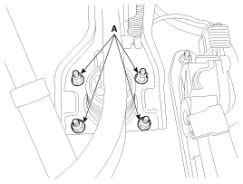
Remove the brake pedal member assembly mounting nuts (A) and then
remove the brake pedal assembly.
|
 Brake Pedal
Components
1. Cowl bracket
2. Brake pedal member assembly
3. Stop lamp switch
4. Return spring
5. Brake pedal
6. Bolt
...
 Inspection
1.
Check the bushing for wear.
2.
Check the brake pedal for bending or twisting.
3.
Check the brake pedal retur ...
See also:
Smart key precautions
If you lose your smart key, you will not be able to start the engine.
Tow the vehicle, if necessary, and contact an authorized Kia dealer.
A maximum of 2 smart keys can be registered to a singl ...
Special Service Tools
Tool Name / Number
Illustration
Description
Alternator pulley remover wrench
09373-27000
Removal and installation of alternator pulley
...
Compressor Components
1. Center Bolt
2. Hub Bolt
3. Disc & Hub Assembly
4. Snap Ring
5. Pulley
6. Compressor Assembly
7. Electric Control Valve (ECV)
...
Copyright ® www.kifomanual.com 2014-2026

