 Kia Forte: Replacement
When the receiver first arrives for replacement:
|
It is important to make sure that the correct receiver is used
to replace the faulty part i.e. it must be Low Line and not High Line
in order to have the correct inflation warning thresholds set.
|
| 1. |
Disconnect the negative (-) battery cable.
|
| 2. |
Remove the center fascia panel.
(Refer to Crash Pad - "Center Fascia Panel")
|
| 3. |
Remove the cluster fascia panel.
(Refer to Crash Pad - "Cluster Fascia Panel")
|
| 4. |
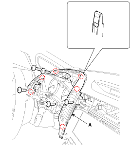
After loosening the mounting screws, then remove the drive airvent
duct assembly (A).
|
| 5. |
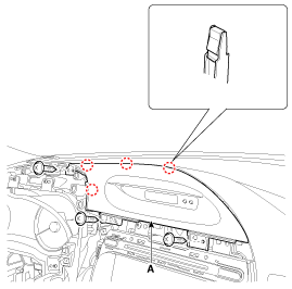
After loosening the mounting screws, then remove the clock fascia
panel (A).
|
| 6. |
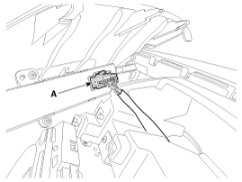
Disconnect the clock switch connector (A).
|
| 7. |
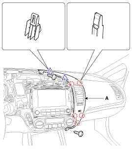
After loosening the mounting screws, then remove the center airvent
duct assembly [RH] (A).
|
| 8. |
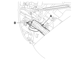
Remove the in-car hose (A).
|
| 9. |
Disconnect the in-car sensor connector (B).
|
| 10. |
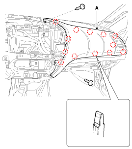
After loosening the mounting screws, then remove the crash pad
upper panel (A).
|
| 11. |
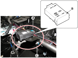
Disconnect the connector (A).
|
| 12. |
Remove the bracket and receiver (B) as loosen the nut (C-1ea).
|
| 13. |
Install in the reverse order of removal.
|
| 14. |
Re-connect battery and turn Ignition on.
|
| 15. |
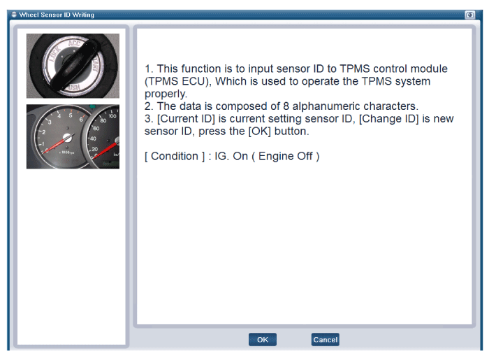
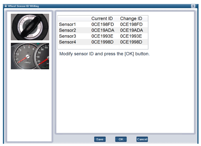
After replacing the receiver, learn by using self-diagnosis device(GDS).
|
[Wheel Sensor ID Writing (Wireless) initialization]
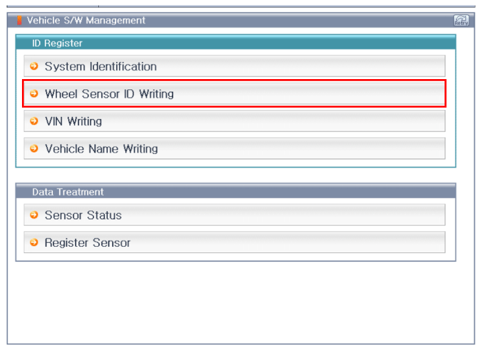
[Wheel Sensor ID Writing (Wireless) 1]
[Wheel Sensor ID Writing (Wireless) 2]
 Operation
1.
General Function
A.
Auto-learn takes place only once per Ignition cycle.
B.
On successful compl ...
 Diagnosis procedure by using diagnostic device
As manual for diagnosis methods by using diagnosis device, the main contents
are as follows:
1.
Connect self-diagnosis connector(16pins) located in the lower
of driv ...
See also:
Input Speed Sensor Description
Input speed sensor is a vital unit that measures the rate of rotation
of the input shaft inside the transaxle and delivers the readings to the Transaxle
Control Module(TCM). The sensor provid ...
Muffler Removal and Installation
Front Muffler
1.
Detach the rubber hanger (A) from the front muffler.
2.
Remove the front muffler (B).
Tightening ...
Removal
1.
Remove the air cleaner assembly.
(Refer to Engine Mechanical System - "Air Cleaner")
2.
Remove the battery and battery tray ...
Copyright © www.kifomanual.com 2014-2025


