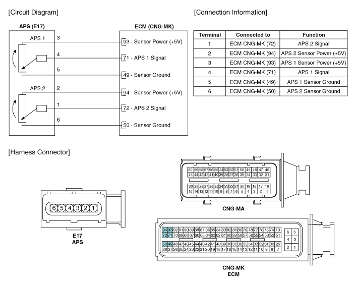
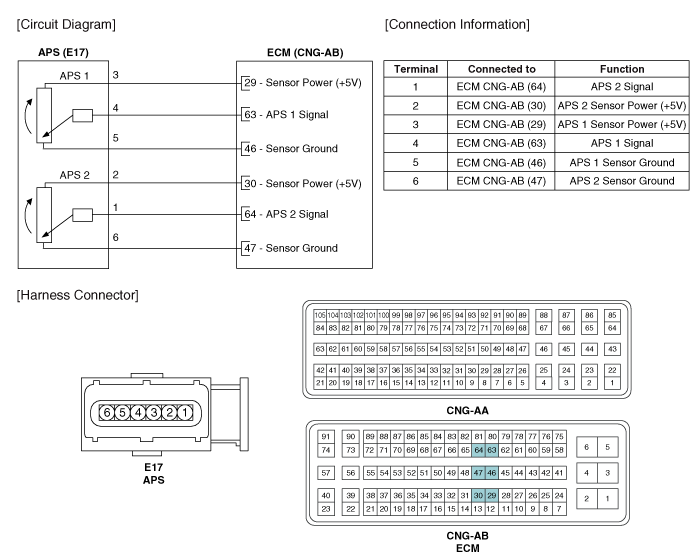
 Kia Forte: Accelerator Position Sensor (APS) Circuit Diagram
Second generation YD (2014-2018) / Kia Forte TD 2014-2018 Service Manual / Engine Control / Fuel System / Engine Control System / Accelerator Position Sensor (APS) Circuit Diagram
| (M/T) |
| (A/T) |
 Accelerator Position Sensor (APS) Specification
Accelerator
Position
Output Voltage (V)
APS1
APS2
C.T
0.7 ~ 0.8
0.29 ~ 0.46
W.O.T
3.85 ~ 4.35
1.93 ~ 2.18
...
 Accelerator Position Sensor (APS) Inspection
1.
Connect the GDS on the Data Link Connector (DLC).
2.
Turn the ignition switch ON.
3.
Measure the output volt ...
See also:
Power Window Switch Circuit Diagram
Driver Power Window Switch
[Driver/Passenger Safety]
[Driver Auto Down]
Passenger Power Window Switch
Rear Power Window Switch
...
Radiator Removal and Installation
1.
Remove the cooling fan.
(Refer to Cooling System - "Cooling Fan")
2.
Remove the radiator upper hose (A).
...
Replacement
ŌĆó
Put on gloves to protect your hands.
...
Categories
- Home
- Kia Forte BD 2019-2026 Owners Manual
- Kia Forte BD 2019-2026 Service Manual
- First Generation
- Second generation
- Kia Forte TD 2014-2018 Owners Manual
- Kia Forte TD 2014-2018 Service Manual

Copyright ® www.kifomanual.com 2014-2026