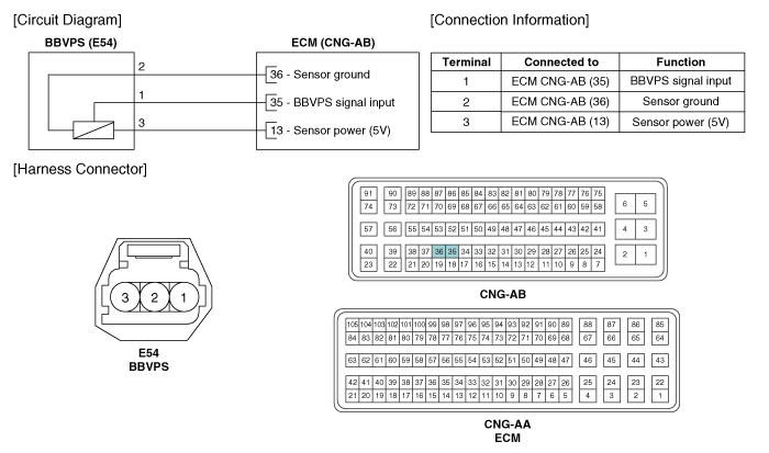
 Kia Forte: Brake Booster Vacuum Pressure Sensor Circuit Diagram
Second generation YD (2014-2018) / Kia Forte TD 2014-2018 Service Manual / Engine Control / Fuel System / ISG (Idle Stop & Go) System / Brake Booster Vacuum Pressure Sensor Circuit Diagram

 Brake Booster Vacuum Pressure Sensor Description
In order to ensure adequate brake power assistance in every situation,
the brake booster is equipped with a partial vacuum sensor. The brake booster
vacuum pressure sensor is located beside t ...
 Brake Booster Vacuum Pressure Sensor Inspection
1.
Check installation status of BBVPS and Vacuum hose or damage of
vacuum hose.
2.
Connect GDS to DLC (Data Link Cable).
...
See also:
Rear Seat Cushion Cover Component Location
1. Rear seat cushion cover
...
Fuel Filler Cap Description
A ratchet tightening device on the threaded fuel filler cap reduces the
chances of incorrect installation, which seals the fuel filler. After the gasket
on the fuel filler cap and the filler ...
Rear Door Outside Handle Component Location
(4Door, 5Door)
1. Rear door outside handle
...
Copyright ® www.kifomanual.com 2014-2026
