 Kia Forte: Engine Mounting Removal and Installation
Second generation YD (2014-2018) / Kia Forte TD 2014-2018 Service Manual / Engine Mechanical System / Engine And Transaxle Assembly / Engine Mounting Removal and Installation
Engine mounting bracket
| 1. |
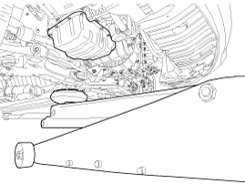
Install the jack to the edge of oil pan to support the engine.
|
| 2. |
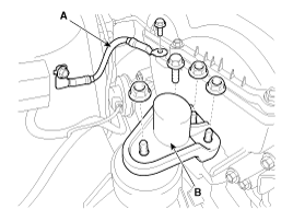
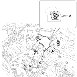
Disconnect the ground cable (A).
|
| 3. |
Remove the engine mounting support bracket (B).
|
| 4. |
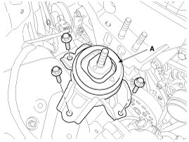
Remove the engine mounting bracket (A).
|
| 5. |
Install in the reverse order of removal.
|
Roll rod mounting support bracket
| 1. |
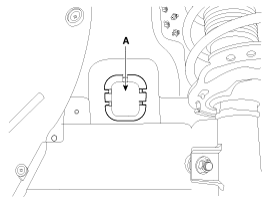
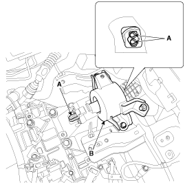
Remove the roll rod bracket (A).
|
| 2. |
Install in the reverse order of removal.
|
Transaxle mounting bracket
| 1. |
Remove the air cleaner assembly.
(Refer to Intake and Exhaust System - "Air Cleaner")
|
| 2. |
Remove the battery and battery tray.
(Refer to Engine Electrical System - "Battery")
|
| 3. |
Install the jack to the edge of transaxle.
|
| 4. |
Remove the transaxle mounting bracket.
|
| 5. |
Install in the reverse order of removal.
|
 Engine Mounting Components
1. Transaxle mounting bracket
2. Roll rod bracket
3. Engine mounting bracket
4. Engine mounting support bracket
...
 Engine And Transaxle Assembly Removal
ŌĆó
Use fender covers to avoid damaging painted surfaces.
Ō ...
See also:
Description
...
Injector Installation
ŌĆó
Install the component with the specified torques.
ŌĆó
...
Overdrive Clutch Control Solenoid Valve(OD/C_VFS) Removal
Replacing an on/off solenoid valve (SS-A, SS-B) does not require
additional hydraulic pressure adjustment; however, the ...
Copyright ® www.kifomanual.com 2014-2026

