
 Kia Forte: Operation
| 1. |
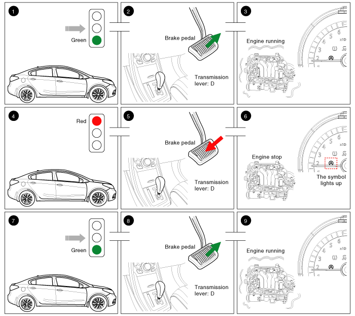
Vehicle moving.
|
| 2. |
The transmission lever position is D-range. The brake pedal is
released.
|
| 3. |
The engine is running. (Vehicle moving).
|
| 4. |
The driver brakes until the vehicle comes to a standstill.
|
| 5. |
The transmission lever position is D-range. The brake pedal is
pressed
|
| 6. |
The engine stops. The symbol "AUTO STOP" lights up in the instrument
cluster.
|
| 7. |
The driver wants to continue the journey.
|
| 8. |
The transmission lever position is D-range. The brake pedal is
released.
|
| 9. |
The engine is running again. The symbol goes out.
|
 Description
Idle Stop & Go (ISG) function automatically switches off the engine when
the car is at a standstill if the and starts it again as soon as the brake pedal
is released. This not only reduce ...
 Operation Condition for the ISG function
1. Auto stop or Auto start condition
(If all of the below condition are satisfied)
Items
State
Remark
Driving conditions
ISG OFF Switch
...
See also:
Blower Unit Components
1. Intake Seal
2. Intake Upper Case
3. Intake Actuator
4. Air Filter
5. Air Filter Cover
6. Intake Door Assembly
7. Intake Lower Case
8. NVH Pad
9. Blower Up ...
Alternator Circuit Diagram
•
COM signal - When
controlling the voltage generated, the ECM sends the target
...
Hood Insulator Pad Replacement
1.
Using a clip remover, detach the clips, and remove the hood insulator
pad (A).
...
Categories
- Home
- Kia Forte BD 2019-2026 Owners Manual
- Kia Forte BD 2019-2026 Service Manual
- First Generation
- Second generation
- Kia Forte TD 2014-2018 Owners Manual
- Kia Forte TD 2014-2018 Service Manual

Copyright © www.kifomanual.com 2014-2026