
 Kia Forte: Installation
Second generation YD (2014-2018) / Kia Forte TD 2014-2018 Service Manual / Brake System / Brake System / Rear Drum Brake / Installation
|

| 1. |
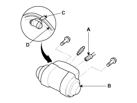
Apply sealant (C) between the wheel cylinder (B) and backing plate
(D), and install the wheel cylinder.
|
| 2. |
Connect the brake tubes (A) to the wheel cylinder.
|
| 3. |
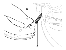
Connect the parking brake cable (A) to the brake shoe.
|
| 4. |
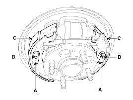
Install the brake shoes (C) onto the backing plate. Be careful
not to damage the wheel cylinder dust covers.
|
| 5. |
Install the shoe hole down pins (B) and the shoe hole down springs
(A).
|
| 6. |
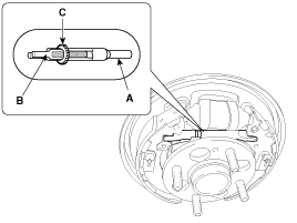
Clean the threaded portions of adjuster sleeve (A) and push rod
female (B). Coat the threads of the adjuster assembly with grease. To
shorten the clevises, turn the adjuster bolt (C).
|
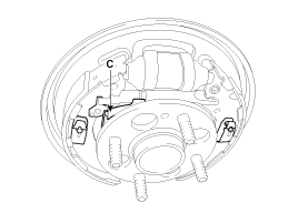
| 7. |
Hook the shoe adjuster lever (C), then install it to the brake
shoe.
|
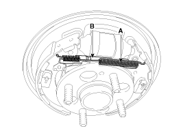
| 8. |
Install the adjuster assembly (B) and upper return spring (A)
as right direction. Be careful not to damage the wheel cylinder dust
covers.
|
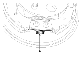
| 9. |
Install the lower return spring (A).
|
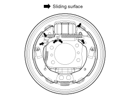
| 10. |
Apply brake cylinder grease or equivalent rubber grease to the
sliding surfaces shown. Don't get grease on the brake linings.
|
| 11. |
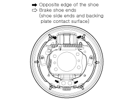
Apply brake cylinder grease or equivalent rubber grease to the
brake shoe ends and opposite edges of the shoes shown. Don't get grease
on the brake linings.
|
| 12. |
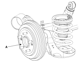
Install the rear brake drum (A).
|
| 13. |
If the wheel cylinder has been removed, bleed the brake system.
|
| 14. |
Depress the brake pedal several times to set the self-adjusting
brake.
|
| 15. |
Adjust the parking brake.
|
 Removal
•
Frequent inhalation of brake pad dust, regardless of material
composition, could be ...
 Inspection
•
Frequent inhalation of brake pad dust, regardless of material
composition, could be ...
See also:
Overdrive Clutch Control Solenoid Valve(OD/C_VFS) Removal
Replacing an on/off solenoid valve (SS-A, SS-B) does not require
additional hydraulic pressure adjustment; however, the ...
Components
1. Timing chain cover
2. Inner roter
3. Outer roter
4. Oil pump cover
5. Relief plunger
6. Relief spring
7. Relief plug
8. O-ring (suction side)
9. O-ring (disch ...
Power Mosfet Inspection
1.
Turn the ignition switch ON.
2.
Manually operate the control switch and measure the voltage of
the blower motor.
3. ...
Categories
- Home
- Kia Forte BD 2019-2026 Owners Manual
- Kia Forte BD 2019-2026 Service Manual
- First Generation
- Second generation
- Kia Forte TD 2014-2018 Owners Manual
- Kia Forte TD 2014-2018 Service Manual

Copyright © www.kifomanual.com 2014-2026