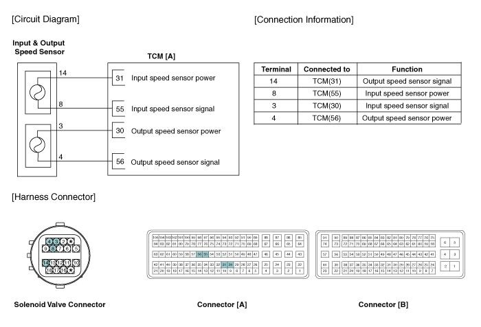
 Kia Forte: Output Speed Sensor Circuit Diagram
Second generation YD (2014-2018) / Kia Forte TD 2014-2018 Service Manual / Automatic Transaxle System / Automatic Transaxle Control System / Output Speed Sensor Circuit Diagram

 Output Speed Sensor Specifications
▷ Type: Hall effect sensor
Operation condition [┬░C(┬░F)]
((-)40 ~ 150)) -40 ~ 302
Air gap(mm)in.
(1.1 ~ 1.55)
0.043 ~ 0.061
Output voltage
...
 Output Speed Sensor Signal Waveform
Fig 1) Input/Output speed sensor at low speed
Fig 2) Input/Output speed sensor at high speed ...
See also:
Components
1. Glass panel assembly
2. Guide assembly
3. Drip rail assembly
4. Sunshade assembly
5. Deflector
6. Deflector link assembly
7. Sunroof frame assembly
8. Motor asse ...
Removal
Handle the sensor with care.
1.
Remove the tire.
(Refer to Tire/Wheels - "Tire& ...
Important Safety Notice
Proper service methods and repair procedures are essential for safe, reliable
operation of all motor vehicles as well as personal safety of the operator.
The service procedures and descriptio ...
Copyright ® www.kifomanual.com 2014-2026
