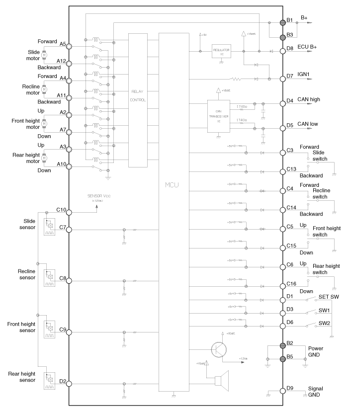
 Kia Forte: Circuit Diagram

 Components
Input/Output Specification
IMS input/output pin information
No.
Signal Name
I/O
Contents
Remark
A1
-
-
-
...
 IMS module Removal
1.
Remove the negative (-) battery terminal.
2.
Remove the driver seat in the car.
(Refer to Body - "Front Seat Assembly")
...
See also:
ETC (Electronic Throttle Control) System Installation
ŌĆó
Install the component with the specified torques.
ŌĆó
...
Rear Wheel Speed Sensor Removal
1.
Remove the rear wheel and tire.
Tightening torque:
88.3 ~ 107.9 N.m (9.0 ~ 11.0 kgf.m, 65.1 ~ 79.6 lb-ft)
...
Certification label
The certification label is located on the driver's door sill at the center pillar.
This label shows the maximum allowable weight of the fully loaded vehicle. This
is called the GVWR (Gross V ...
Copyright ® www.kifomanual.com 2014-2026
