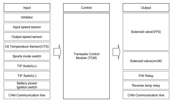
 Kia Forte: Circuit Diagram

 Adjustment
Transaxle Control Module(TCM) Learning
When shift shock is occurred or parts related with the transaxle are replaced,
TCM learning should be performed.
In the following case, TC ...
 Components Location
1. Automatic transaxle
2. Inhibitor switch
3. Transaxle Control Module (TCM)
4. Valve body cover
5. Solenoid valve connect
6. Oil temperature sensor
7. Valve body assembly ...
See also:
Knock Sensor (KS) Specification
Item
Specification
Capacitance (pF)
850 ~ 1,150
...
Blower Unit Replacement
1.
Disconnect the negative (-) battery terminal.
2.
Remove the heater and blower assembly.
(Refer to Heater - "Heater Unit")
...
Rear Wheel House Trim Component Location
(4Door)
1. Rear wheel house trim
(5Door)
1. Rear wheel house trim
...
Copyright ® www.kifomanual.com 2014-2026
