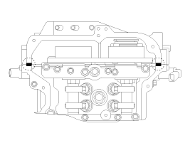
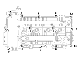
 Kia Forte: Cylinder Head Cover Installation
Second generation YD (2014-2018) / Kia Forte TD 2014-2018 Service Manual / Engine Mechanical System / Cylinder Head Assembly / Cylinder Head Cover Installation
| 1. |
Install cylinder head cover.
|
| 2. |
Install the other parts reverse order of removal.
|
 Cylinder Head Cover Removal
ŌĆó
Use fender covers to avoid damaging painted surfaces.
Ō ...
 CVVT & Camshaft Components
1. Camshaft bearing cap
2. Camshaft front bearing cap
3. Exhaust camshaft
4. Intake camshaft
5. Exhaust CVVT assembly
6. Intake CVVT assembly
...
See also:
Front Cross Member
* These dimensions indicated in this figure are
actual-measurement dimensions. [ Unit : mm (inch) ]
...
Accelerator Position Sensor (APS) Description
Accelerator Position Sensor (APS) is installed on the accelerator pedal
module and detects the rotation angle of the accelerator pedal. The APS is one
of the most important sensors in engine ...
System settings
Press the
key
Select [System]
Select menu through
TUNE knob
Memory Information
Displays currently used memory and total system memory.
Select [Memory Information]
OK ...
Copyright ® www.kifomanual.com 2014-2026


