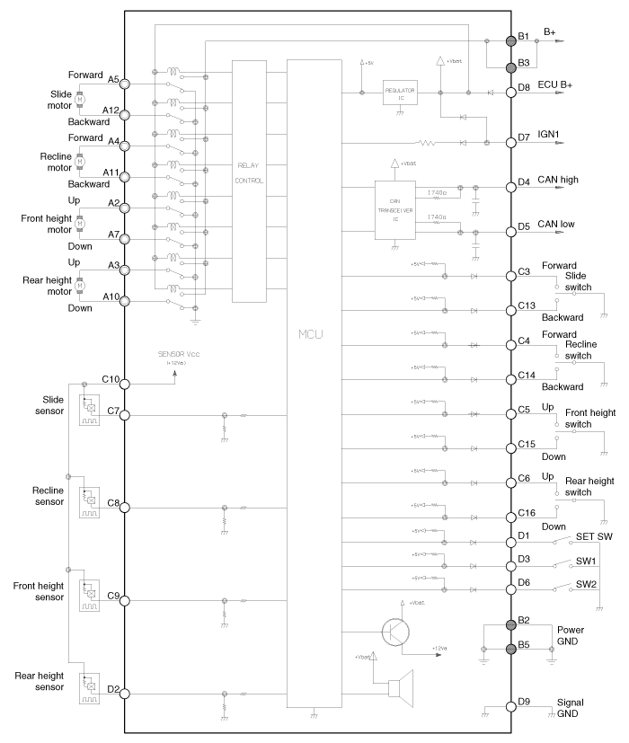
 Kia Forte: Circuit Diagram

 Components
Input/Output Specification
IMS input/output pin information
No.
Signal Name
I/O
Contents
Remark
A1
-
-
-
...
 IMS module Removal
1.
Remove the negative (-) battery terminal.
2.
Remove the driver seat in the car.
(Refer to Body - "Front Seat Assembly")
...
See also:
Component Location
1. EMS box assembly
(Engine control relay, Fuel pump relay,
Air conditioner compressor relay)
2. C/Fan 1 relay
3. C/Fan 2 relay
4. SSB 4(IG2) relay
5. Blower relay
...
SS-B Solenoid Valve(ON/OFF) Circuit Diagram
...
Components of the Tire Mobility Kit
0. Speed restriction label
1. Sealant bottle and label with speed restriction
2. Filling hose from sealant bottle to wheel
3. Connectors and cable for the power outlet direct connection
4. Hol ...
Copyright © www.kifomanual.com 2014-2025
