
 Kia Forte: Inhibitor Switch Circuit Diagram
Second generation YD (2014-2018) / Kia Forte TD 2014-2018 Service Manual / Automatic Transaxle System / Automatic Transaxle Control System / Inhibitor Switch Circuit Diagram
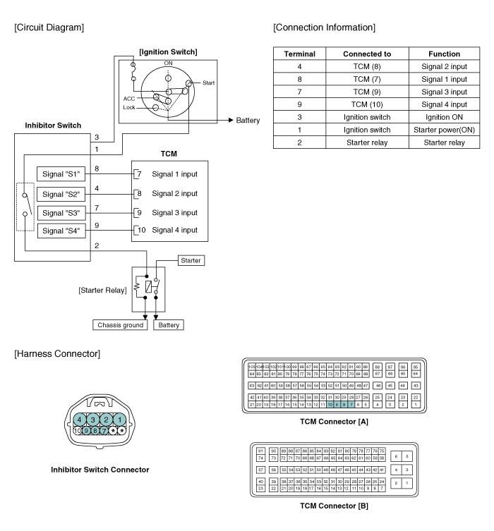
 Inhibitor Switch Specifications
▷ Type: Combination of output signals from 4 terminals
Power supply (V)
12
Output type
Combination of output signals
Signal Code Table
...
 Inhibitor Switch Inspection
•
Thoroughly check connectors for looseness, poor connection,
bending, corrosion, cont ...
See also:
Removal
The side airbag cannot be disassembled from the seat back assembly,
so replace assembly when replacing the side airbag.
...
Heater & A/C Control Unit (Manual) Components
Connector Pin Function
Connector
No.
Description
Connector
No.
Description
A
1
Ground
B
14
In ...
Operation
1.
General Function
A.
Auto-learn takes place only once per Ignition cycle.
B.
On successful compl ...
Categories
- Home
- Kia Forte BD 2019-2026 Owners Manual
- Kia Forte BD 2019-2026 Service Manual
- First Generation
- Second generation
- Kia Forte TD 2014-2018 Owners Manual
- Kia Forte TD 2014-2018 Service Manual

Copyright � www.kifomanual.com 2014-2026