 Kia Forte: Front Hub / Knuckle Replacement
Second generation YD (2014-2018) / Kia Forte TD 2014-2018 Service Manual / Driveshaft and axle / Front Axle Assembly / Front Hub / Knuckle Replacement
| 1. |
Loosen the wheel nuts slightly.
Raise the vehicle, and make sure it is securely supported.
|
| 2. |
Remove the front wheel and tire (A) from front hub .
|
| 3. |
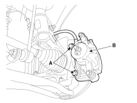
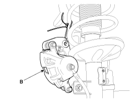
Remove the brake caliper mounting bolts (A), and then place the
brake caliper assembly (B) with wire.
|
| 4. |
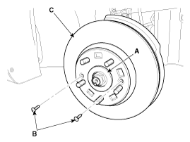
Loosen the coking nut (A) and screw (B) then remove the front
brake disc (C).
|
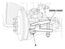
| 5. |
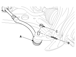
Remove the tie rod end ball joint (A) from the knuckle.
|
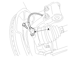
| 6. |
Loosen the mount bolt and then remove the wheel speed sensor (A)
from knuckle.
|
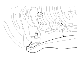
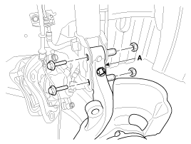
| 7. |
Remove the lower arm (A) from the knuckle.
|
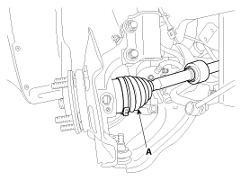
| 8. |
Disconnect the driveshaft (A) from the front hub assembly.
|
| 9. |
Loosen the strut mounting bolts and then remove the knuckle assembly
(A).
|
 Front Hub / Knuckle Components
1. Drive shaft coking nut
2. Brake disc
3. Wheel hub assembly
4. Wheel bearing
5. Snap ring
6. Dust cover
7. Knuckle
8. Drive shaft
...
 Front Hub / Knuckle Disassembly
1.
Remove the snap ring (A).
2.
Remove the hub assembly from the knuckle assembly.
(1)
Install the ...
See also:
Overdrive Clutch Control Solenoid Valve(OD/C_VFS) Removal
Replacing an on/off solenoid valve (SS-A, SS-B) does not require
additional hydraulic pressure adjustment; however, the ...
Variant coding
After replacing the SRSCM with a new unit, the ŌĆ£Variant CodingŌĆØ procedure
must be performed.
1.
...
Cluster Fascia Panel Replacement
ŌĆó
Put on gloves to protect your hands.
...
Copyright ® www.kifomanual.com 2014-2025


