 Kia Forte: Installation
Second generation YD (2014-2018) / Kia Forte TD 2014-2018 Service Manual / Brake System / Brake System / Brake Pedal / Installation
| 1. |
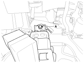
Pre-tighten the bracket fixing bolt (A) in dash panel.
|
| 2. |
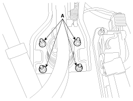
Install the brake booster and brake pedal member fixing nuts (A)
securely.
|
| 3. |
Tighten the bolt (A) securely in dash panel.
|
| 4. |
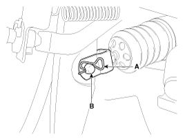
Install the snap pin (A) and clevis pin (B).
|
| 5. |
Install the stop lamp switch securely.
|
| 6. |
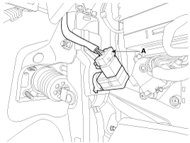
Connect the stop lamp switch connector (A).
|
| 7. |
Adjust the brake pedal height and free play.
|
| 8. |
Check the brake pedal operation after installing the brake pedal.
|
| 9. |
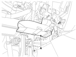
Install the shower duct (A).
|
| 10. |
Install the crash pad lower panel.
(Refer to Body - "Crash pad lower panel")
|
| 11. |
Reconnect the battery negative cable.
|
 Inspection
1.
Check the bushing for wear.
2.
Check the brake pedal for bending or twisting.
3.
Check the brake pedal retur ...
 Adjustment
Stop lamp switch clearance adjustment
If the gap between stop lamp switch and bracket is not 1.0 ~ 2.0mm(0.04~
0.08in), conform to below.
1.
Disconnect the s ...
See also:
Sunvisor
Use the sunvisor to shield direct light through the front or side windows.
To use the sunvisor, pull it downward. To use the sunvisor for the side window,
pull it downward, unsnap it from the br ...
Input Speed Sensor Description
Input speed sensor is a vital unit that measures the rate of rotation
of the input shaft inside the transaxle and delivers the readings to the Transaxle
Control Module(TCM). The sensor provid ...
Compressor Oil Specification
1.
The R-134a system requires synthetic compressor oil (PAG) whereas
the R-12 system requires mineral compressor oil. The two oils must never
be mixed.
...
Copyright ® www.kifomanual.com 2014-2025

