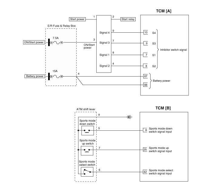
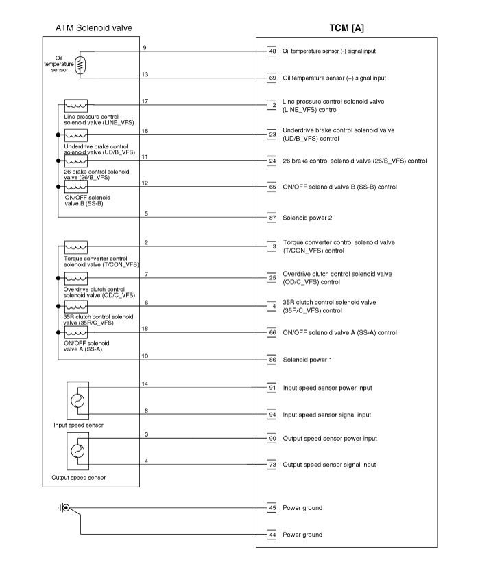
 Kia Forte: Transaxle Control Module (TCM) Circuit Diagram
Second generation YD (2014-2018) / Kia Forte TD 2014-2018 Service Manual / Automatic Transaxle System / Automatic Transaxle Control System / Transaxle Control Module (TCM) Circuit Diagram


 TCM Terminal Input/ Output Signal
Connector [A]
Pin
Description
Condition
Input/output value
Type
Level
1
-
...
 Transaxle Control Module (TCM) Inspection
Transaxle Control Module(TCM) Problem Inspection Procedure
1.
TEST TCM GROUND CIRCUIT: Measure resistance between TCM and chassis
ground using the backside of TCM harne ...
See also:
Torque Converter Control Solenoid Valve (T/CON_VFS) Inspection
1.
Turn ignition switch OFF.
2.
Disconnect the Solenoid valve connector.
3.
Measure resistance between sensor ...
Front Body
Front Body A
* These dimensions indicated in this figure are
actual-measurement dimensions. [ Unit : mm (inch) ]
Front Body B
* These dimensions indicated in th ...
Copyright ® www.kifomanual.com 2014-2026
