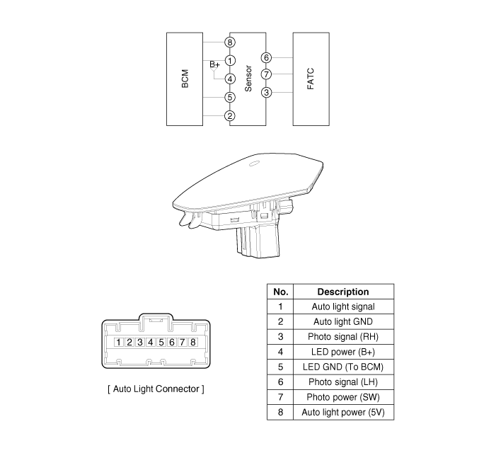
 Kia Forte: Circuit Diagram

 Component Location
1. Auto light sensor
2. Head lamps
3. Lighting switch (Auto)
4. Tail lamps
5. Body control module (BCM)
...
 Auto Light Sensor Inspection
In the state of IGN1 ON, when multifunction switch module detects auto
light switch on, tail lamp relay output and head lamp low relay output are controlled
according to auto light sensor' ...
See also:
CVVT Oil Control Valve (OCV) Description
Continuous Variable Valve Timing (CVVT) system advances or retards the
valve timing of the intake and exhaust valve in accordance with the ECM control
signal which is calculated by the engine ...
Air Ventilation Seat Unit Components Location
Components Location (1)
1. Seat back blower
2. Seat cushion blower
3. Air ventilation unit
4. Air ventilation switch
Components Location (2)
Components Locati ...
OBD-II review
1. Overview
The California Air Resources Board (CARB) began regulation of On Board
Diagnostics (OBD) for vehicles sold in California beginning with the 1988 model
year. The first phase, O ...
Copyright ® www.kifomanual.com 2014-2026
