
 Kia Forte: Input Speed Sensor Circuit Diagram
Second generation YD (2014-2018) / Kia Forte TD 2014-2018 Service Manual / Automatic Transaxle System / Automatic Transaxle Control System / Input Speed Sensor Circuit Diagram
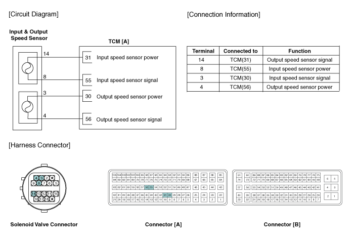
 Input Speed Sensor Specifications
▷ Type: Hall effect sensor
Operation condition [°C(°F)]
((-)40 ~ 150)) -40 ~ 302
Air gap(mm)in.
(1.2 ~ 1.8)
0.0472 ~ 0.0709
Output voltage ...
 Input Speed Sensor Signal Waveform
Fig 1) Input/Output speed sensor at low speed
Fig 2) Input/Output speed sensor at high speed ...
See also:
Start/Stop Button Removal
1.
Disconnect the negative (-) battery terminal.
2.
Using a screwdriver or remover, remove the center garnish [LH]
(A).
...
Operation Condition for the ISG function
1. Auto stop or Auto start condition
(If all of the below condition are satisfied)
Items
State
Remark
Driving conditions
ISG OFF Switch
...
Water pump Troubleshooting
Symptoms
Possible Causes
Remedy
Coolant leakage
•
From the bleed hole of the water pump
Visually ...
Categories
- Home
- Kia Forte BD 2019-2026 Owners Manual
- Kia Forte BD 2019-2026 Service Manual
- First Generation
- Second generation
- Kia Forte TD 2014-2018 Owners Manual
- Kia Forte TD 2014-2018 Service Manual

Copyright © www.kifomanual.com 2014-2026