
 Kia Forte: Oil Pump Unit (OPU) Circuit diagram
Second generation YD (2014-2018) / Kia Forte TD 2014-2018 Service Manual / Engine Control / Fuel System / ISG (Idle Stop & Go) System / Oil Pump Unit (OPU) Circuit diagram
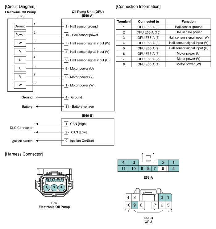
 Oil Pump Unit (OPU) Connector
Opu Connector Terminal Function
E56-A
E56-B
Pin No.
Description
Pin No.
Description
1
Motor power(W)
1
...
 Oil Pump Unit (OPU) Removal
1.
Remove the negative (-) battery terminal.
2.
Remove the crash pad lower panel.
(Refer to Body - “Crash Pad”)
...
See also:
Cylinder Head Installation
•
Thoroughly clean all parts to be assembled.
•
...
CVVT Oil Control Valve (OCV) Inspection
1.
Turn the ignition switch OFF.
2.
Disconnect the OCV connector.
3.
Measure resistance between the OCV termina ...
Components
1. Hands free call switch
2. Mic
3. Front left speaker
4. Front right speaker
5. Audio head unit (hands free control)
※ There is no hands free jack. ...
Categories
- Home
- Kia Forte BD 2019-2026 Owners Manual
- Kia Forte BD 2019-2026 Service Manual
- First Generation
- Second generation
- Kia Forte TD 2014-2018 Owners Manual
- Kia Forte TD 2014-2018 Service Manual

Copyright © www.kifomanual.com 2014-2026