
 Kia Forte: Starter Description
Second generation YD (2014-2018) / Kia Forte TD 2014-2018 Service Manual / Engine Control / Fuel System / ISG (Idle Stop & Go) System / Starter Description
The starting system includes the battery, starter, solenoid switch, inhibitor
switch (A/T), ignition switch, ignition lock switch, connection wires and the
battery cable.
When the ignition key is turned to the start position, current flows and
energizes the starter motor's solenoid coil.
The solenoid plunger and clutch shift lever are activated, and the clutch
pinion engages the ring gear.
The contacts close and the starter motor cranks. In order to prevent damage
caused by excessive rotation of the starter armature when the engine starts,
the clutch pinion gear overruns.
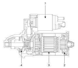
In conjunction with the ISG function, the starter motor must do a great
deal more work. The starter motor is therefore configured for a significantly
higher number of start cycles. The components of the starter motor have been
adapted to the higher requirements.
There are two kinds of starter, ISG type starter and the other.
When replace the starter, confirm that the part number and connector
shape.
|

ISG (Idle stop & go) system equipped vehicle always use the ISG
type starter only. If the other starter has installed, this can potentially
lead to engine electrical trouble or ISG system error.
|

Do not disassemble the ISG type starter.
If the starter troubles occur, replace the starter.
|

 Alternator Intallation
1.
Install in the reverse order of removal.
Adjust the alternator belt te ...
 Starter Removal
1.
Disconnect the battery negative (-) cable.
2.
Remove the air duct and air cleaner assembly.
(Refer to Engine Mechanical System - &qu ...
See also:
Seat belt restraint system
Seat belts are designed to bear upon the bony structure of the body, and should
be worn low across the pelvis, chest and shoulders as applicable. Wearing the lap
section of the belt across the abdom ...
Injector Installation
•
Install the component with the specified torques.
•
...
Scheduled maintenance service
Follow the Normal Maintenance Schedule if the vehicle is usually operated where
none of the following conditions apply. If any of the following conditions apply,
follow the Maintenance Under Severe ...
Categories
- Home
- Kia Forte BD 2019-2026 Owners Manual
- Kia Forte BD 2019-2026 Service Manual
- First Generation
- Second generation
- Kia Forte TD 2014-2018 Owners Manual
- Kia Forte TD 2014-2018 Service Manual

Copyright � www.kifomanual.com 2014-2026